I started getting back into electronics recently. My eventual goal is to create a robotic team mascot for my team at work. My first, humble part of that project was to create a charger for the robot's batteries. After weeks of waiting for parts to arrive, being too busy to work on it, and accidentally destroying it, I finally finished it today. Yippee!
I wanted a battery charger that could charge the various NiMH battery packs that I have, ranging from 700 mAh to 2200 mAh and 1.2 V to 7.2 V, and be cheaper than the single-purpose chargers sold at the store. I got some general information about battery charging from http://www.mpoweruk.com/chargers.htm and more specific ideas for a charger from http://www.angelfire.com/electronic/hayles/charge1.html.
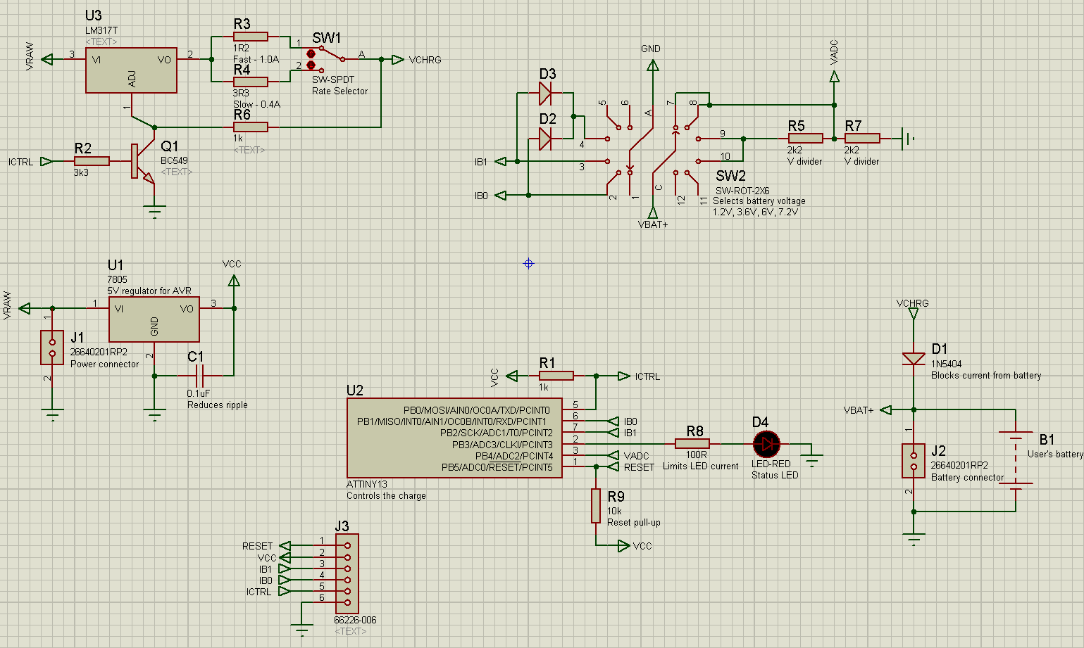
(schematic)
The operation is as follows:
- The rate switch sets the maximum charge rate, 0.4 amps in the slow setting and 1 amp in the fast setting. The charger software will charge at some portion of that maximum rate.
- The voltage selection switch allows the battery pack voltage to be selected. The charger is designed for 1.2V, 3.6V, 6V, and 7.2V battery packs, but there is some flexibility and these values could be changed in software. The switch is a double pole rotary switch, which allows it to simultaneously inform the microcontroller of the selection and control a voltage divider to halve the voltage from the battery packs over 4V (since the microcontroller's ADC can only read voltages up to VCC, which is 5V, and a fully-charged pack supplies about 1.25 times its nominal voltage).
- Status and state changes are communicated by various patterns of flashes on the status LED.
The software was written from scratch, using logic similar to that described on the above charger page, but with many changes. I incorporated voltage-based termination in addition to negative delta-V and time-based charge termination, removed the trickle charging, added a third charging phase, used more sophisticated battery detection logic, and designed the charger for very low power usage when not actively charging. Squeezing everything into 1024 bytes was quite a challenge, but with some fun and ugly hacks I was able to fit all of the features I wanted.
Features of the software:
- API for communicating with PCs over serial ports, used for debugging.
- Use of CPU sleep modes to save power and increase ADC accuracy.
- Pulse width modulation to control the charge current.
- Use of the watchdog timer and sleep modes for low-power delays.
- Power-on self test
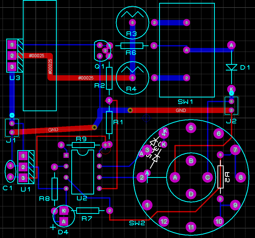
(layout)
Unfortunately, ARES has no support for prototyping boards, so I created an overlay of the islands using the silkscreen layer in ARES, and just routed it as though it was a PCB. I didn't actually plan to use vias or solder-side wiring in the real thing, with the exception of R5, D2, and D3 (behind the rotary switch), and I expected that the jumper wires would take slightly different paths than the traces shown in the layout.
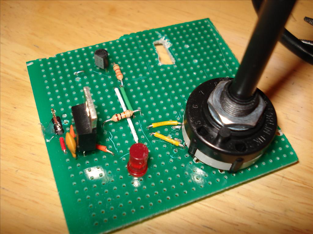
Before I could even begin construction, I had to get some tools so I could cut and drill the prototype board. That took two weeks. While I was waiting, I constructed the circuit on a breadboard, debugged the code, and charged my first battery pack. When I finally got the tools, I quickly noticed that the layout wouldn't quite work, due to jumper wires being trickier to place than I thought. (They don't like being overlapped.) Routing the ISP header became too complicated, so that feature never made it in. Here you can see an early stage with my highly professional construction techniques evident, and the first few parts soldered on. Most of the scratches are my poor-man's silkscreen, but some are just scratches. I used hot glue to hold some parts in place, especially those that would be manipulated or seemed potentially unstable.
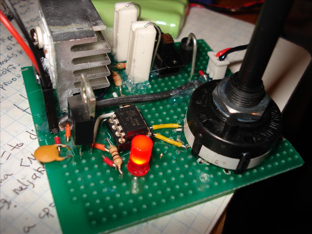
It was very difficult to cut the hole for the slide switch — I used through-panel because I didn't have any PCB-mount switches — and you can see the mess of incorrectly-placed drill holes under the rotary switch. The rotary switch didn't use the standard 0.1" grid spacing for its pins, so all the holes had to be drilled manually. I worked by drilling one hole, placing the switch on it, seeing where other pins happened to be sitting, and then trying to remember their locations while I drilled the next hole. It was a mess. After I finished, I got the idea to press the switch onto a piece of paper to get indentations matching the pin locations, and then attach the paper to the board and drill the holes through it. Might work.
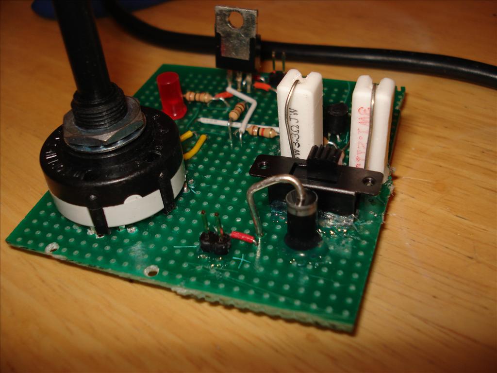
Here it is with a few more components soldered on. The switch was only rated for 0.6 amps, despite me needing to put 1 amp through it. I assumed it was 0.6 amps per pole, and since it was a double-pole switch, I just connected both poles together to double the rating. Might work!
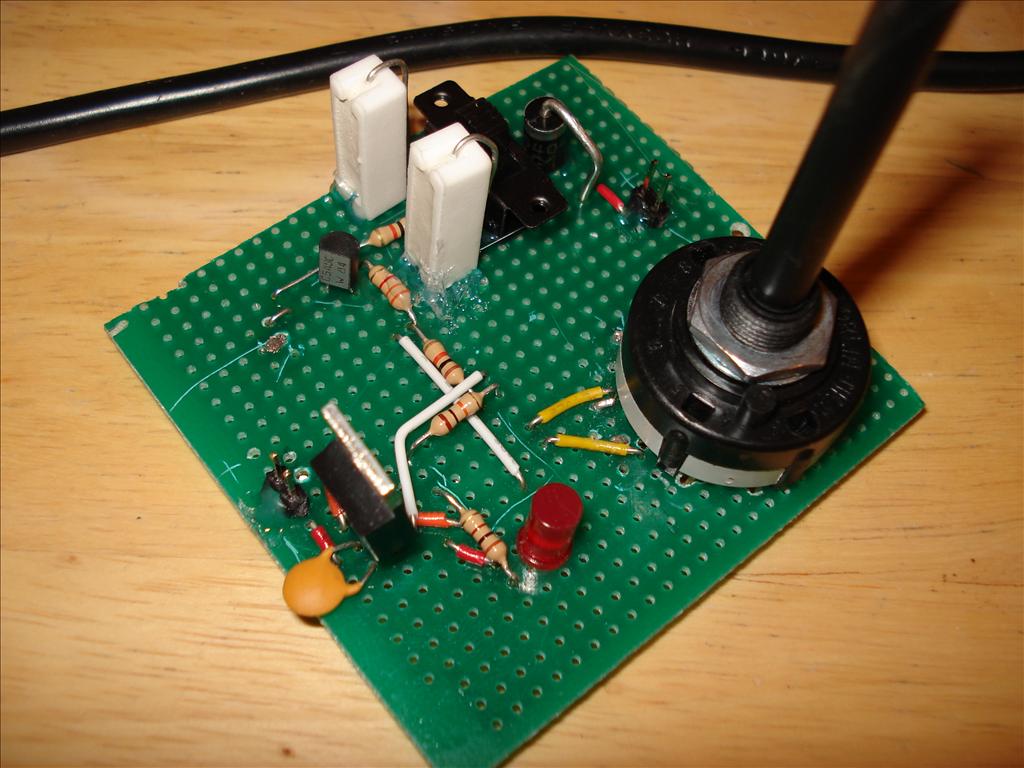
In the pictures below, it was almost done, or so I thought. I was just waiting to receive the two resistors for the voltage divider, and some thermal grease for the adjustable regulator's heatsink.
After receiving the parts and soldering everything on, I tested all the connections with a multimeter to make sure there weren't any accidental shorts. I added the microprocessor and powered it up. The quick flashes told me that it had failed the power-on self test. A bit of investigation revealed that I'd forgotten to connect a wire to ground from the emitter of the transistor, causing the charge current to be always on. I simply added that wire, and it passed the test.
Then I connected a battery pack and... nothing, and then smoke, and then melting! I tried to quickly locate the source and saw that smoke was beginning to pour out of the battery pack. Yikes! I pulled it out and it was really hot. I put it on the stove in case it decided to explode or burst into flames. It turns out that last wire I added shorted some adjacent pads, effectively shorting the battery terminals. I thought the change was so small that I wouldn't need to test it with the multimeter... there's a lesson in there somewhere.
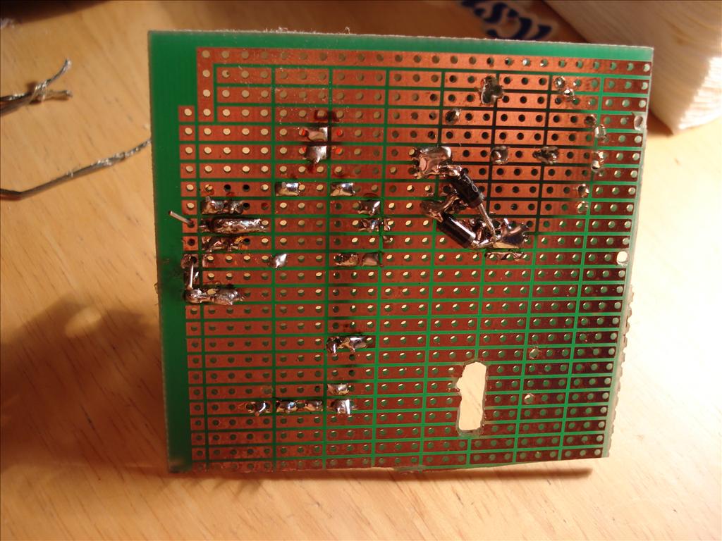
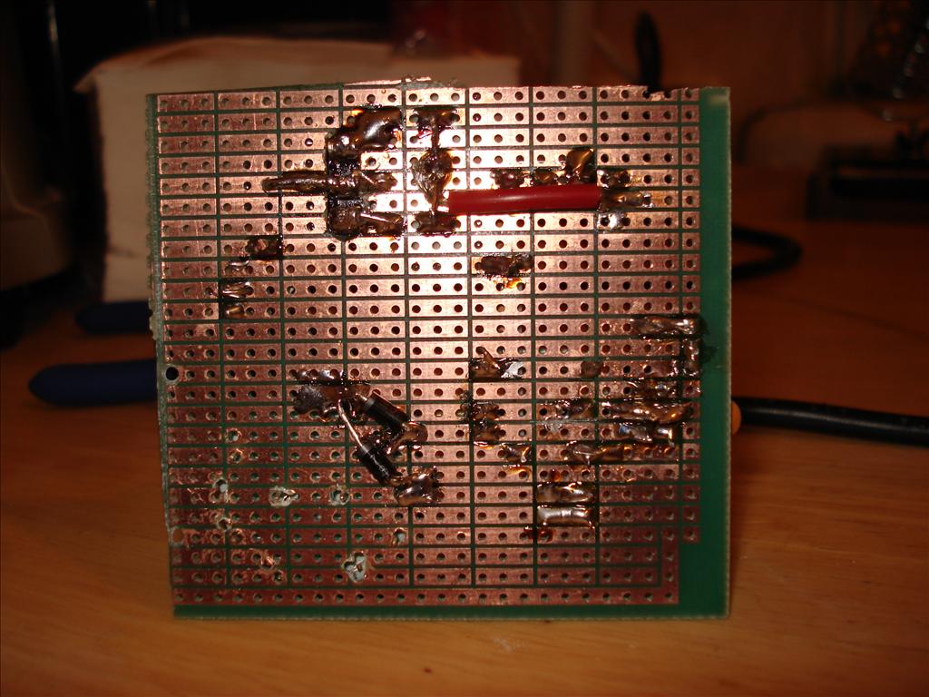
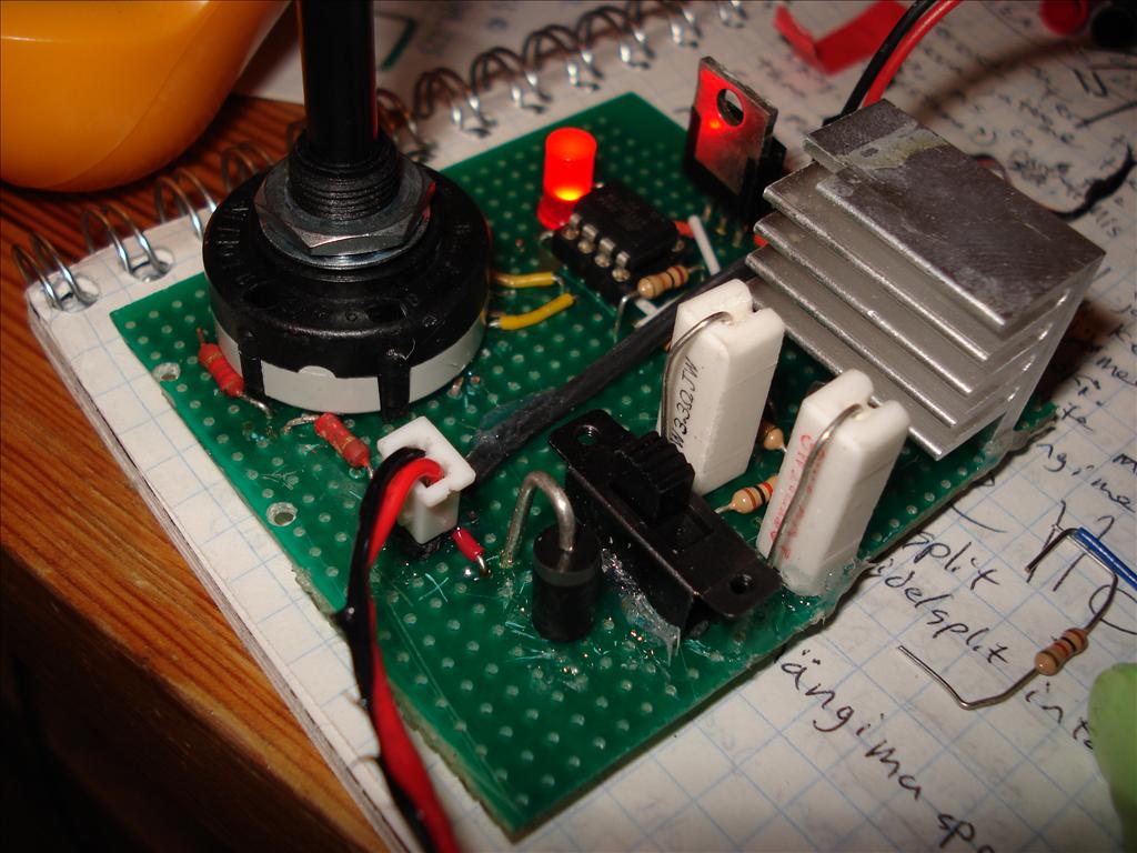
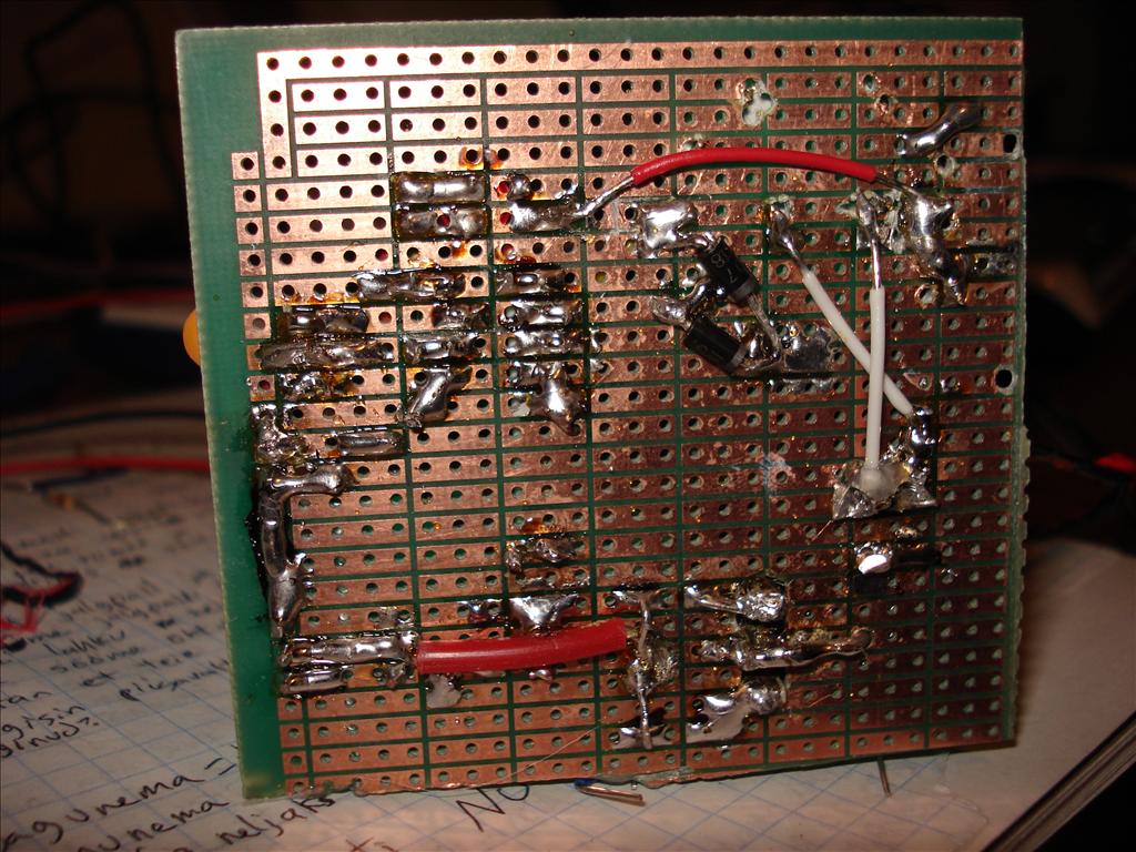
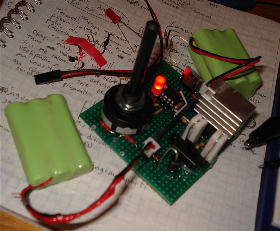
After fixing it, I tried plugging the battery pack back in. The microcontroller powered up, which shouldn't have happened. Apparently the meltdown fried my diode, and now the battery power was flowing into the rest of the circuit. I had another one, though, so I replaced it, but apparently I took too long to solder it and the heat destroyed that diode too. It was my last power diode, so I set the project aside and ordered more parts. Finally I got them and now it works. Yay! Here it is, recharging my melted battery pack. Most of the wires on the bottom were the result of insufficient planning.
As a finishing touch, I'll cut the long stem of the rotary switch and attach a proper knob to it, once I receive the necessary hex key. And that'll be that. I was impressed with the ATtiny's ability to withstand abuse. Several times I accidentally connected it to high voltage, bent its pins, interrupted its programming, and wired things up wrongly, but it kept on ticking. The source code, compiled binary, schematic, and layout are all here, if you're curious or would like to try building your own charger.
Additionally, you can use the charger to get infinite energy by using one battery pack to charge another, as shown below. When it runs out, just switch them around!
TTFN!
Comments